A preliminary examination of the pole support phases from first to second take-off has to be made to keep this discussion based on universally understood mechanical and biomechanical definitions and concepts.
These concepts can then be properly applied to pole vaulting in general as well as to an analysis of the specific vaulting techniques used by Sergei Bubka and Renaud Lavillenie.
The analysis is limited to being merely qualitative because reliable, scientifically obtained quantitative data on the two vaulters in question are not readily available in the public domain. This is particularly the case for the most recent performances of the technique currently (2014) used by Renaud Lavillenie.
Unravelling “beliefs” in regard to the way in which “conservation laws” (of energy or momentum) operate in this vital part of the total vault process necessitates keeping the discussion focussed on accurate descriptions that can be universally accepted and understood as being supported by both physical mechanical laws and very strong empirical evidence. Of equal importance the “face validity” of claims and assertions in regard to the technique currently used by Renaud Lavillenie in 2013 -2014 need to be evaluated.
Qualitative video / film evidence from the recorded images of pole vault performances by both Bubka and Lavillenie is readily obtainable from the analysis of recordings obtained from internet sources and forms the major source of technique performance evidence upon which my contribution to this discussion will be based.
What follows in this and some additional posts is an attempt to assist readers and myself in clarifying conceptual understanding of the pole support phases of the vault and to propose a mechanics based rationale to account for the relative successes of PB (Petrov-Bubka Technique: specific to Sergei Bubka) and the technique termed “Tuck and Shoot” specifically performed most recently (post 2012 Olympic Games to July 2014) by Renaud Lavillenie.

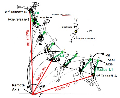
- Local and remote axes of pole rotation top hand and pole tip respectively.jpg (66.13 KiB) Viewed 32307 times
First some definitions and explanation of the diagram above.
Diagram definitions:
1st take-off, foot / toes of the take-off leg breaks contact with the runway surface) instant 1.
2nd take-off, the first observable instant when the vaulter having completed the inversion spiral (approximate) 180 degree turn about the local axis of the vaulter’s the upper grip location length along the pole is released and the vaulter commences flight at instant 8 in the drawing).
Curvilinear pathway, the actual path followed by the vaulter’s centre of mass (COM) resulting from non-uniform motion with combining rotation and translation. The pathway is indicated by the dashed black curve traced out during the motion sequence by the vaulter’s COM.
Radius L, the radial distance from the top of the top grip on the pole to the centre of mass of the vaulter.
Radius R, the radial distance from the vaulter’s centre of mass (COM) to the pole tip located at the deepest location in the planting box.
+M, the anticlockwise moment about a local or remote X,Y,Z rotation axis.
-M, the clockwise moment about a local or remote X,Y,Z rotation axis.
Numbers on the diagram, refer to the body segment configuration and COM location at selected instants in time during the pole support continuous action sequence from take-off to final pole release by the top grip hand.
Diagram Explanatory Notes:1. The diagram drawings were made from film of Sergei Bubka and represent “snapshots” at selected instants in the continuous action sequence of the pole support phases of the vault. The pathway of the vaulter’s COM was determined from cine film using frame by frame segmental analysis method. The pathway COM XY coordinates from all the still frame images were plotted on to the frame by frame images and transposed to the diagram made from copying the images by means of contour drawing. The resulting XY plot was smoothed and transferred to the selected image diagram shown above.
2. At instant 1 the toe tip is breaking ground contact at take-off following the completion of the pole plant that linked the approach run and pole carry and take-off foot ground contact.
Note the relative location of the top grip hand to the vaulter’s COM which is moving forward and upward in the same plane (XY) at the instant the take-off toe breaks ground contact. The COM is well in advance of the position of the top hand as take-off occurs. The full implications of this fact will be elaborated in my next post. 3. The Green Cross circle is located at the position along the pole of the top hand grip. The straight line linking this point to the vaulter’s centre of mass (COM) Radius L1 is the radial distance from the vaulter local axis of rotation (transverse horizontal axis) to the vaulter’s COM. Note the height of the vaulter COM and its horizontal distance in advance of the take-off foot toe tip.
4. The vaulter’s COM , Black and Yellow Cross Circle, has a Radius R1 from the pole tip (Remote Axis: transverse horizontal (Z) axis at take-off with the understanding that at the pole tip rotation has multiple axes throughout the course of the pole support phases).
5. The dashed (black) curve is the 2-D smoothed curvilinear pathway in the XY plane of the vaulter’s COM.
Note firstly that this indicates that the rise (vertical elevation) rate of the COM varies throughout both bending and recoil phase of pole support. The rise rate rapidly increases just before maximum pole bend and continues this positive rise rate until about instant 7. The COM rise rate then decreases during the lower hand pole release from instant 7 and final pole release occurs at instant 8. After this instant the vertical rise is subject to a constant acceleration in the negative y direction and the vaulter is in post 2nd take-off flight ascent phase until peak flight height of the COM is reached.6. The curvilinear pathway of the COM during the bending of the pole reveals that the vaulter’s muscular effort and momentum transfer to it, is dominated by the resultant tangential forces and torques.
Note the vaulter induced forces / torques and the speed at which they are generated (Power) dictate the rate and amplitude of pole bending in the 1st Pole Support Phase depending upon the elasticity characteristics of the pole selected for this particular vault.
The total system COM horizontal displacement forwards towards the plane of the crossbar, due to the associated pole bending and lateral “snap deflection,” carries the total system centre of mass more rapidly horizontally forward compared to its speed of vertical ascent. This is confirmed by the change in slope of the vaulter’s COM curvilinear pathway depicted on the diagram from instant 1 to just about instant 3.
After this point in time the rate of COM rise climbs rapidly until about instant 5 when the vaulter’s clockwise (-ve) rotation about the top grip and mid shoulder axes has enabled both lower limbs to align approximately parallel with the upper and lower grip section of the pole (“covering the pole”).The “swinging backward - roll up” into maximum pole bend that ends phase one of pole support.

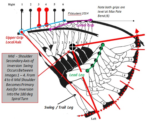
- Back roll up to inversion via the secondary mid - shoulder axis.jpg (97.9 KiB) Viewed 32307 times
(My drawings in diagram 2 above were made using the methods previously described. It is taken from a different vault by Bubka and is approximately equivalent to what occurs between instants3 to 4 in the first diagram).The diagram above illustrates how Sergei Bubka changes his swing rotation axis from primarily about the top grip towards the mid shoulders thereby accelerating
the already forced pendular swing to increase the magnitude of the tangential velocity of his COM and of the foot of the swing leg directed vertically upward at about the same time that maximum pole bend occurs.
This subtle rotational axis shifting creates an increase in linear tangential velocity of the vaulter’s COM about the top hand and at the same time produces a very large increase in the magnitude of the vertical momentum component that is coincident in time and direction with the start of the pole recoil impetus applied to the vaulter. This axis shift may also slightly increase the duration of the time during which the vaulter is able to maintain and or apply additional muscle generated torques to accelerate the extended leg swing whilst at this same time gaining additional arc length travel distance in the swing.
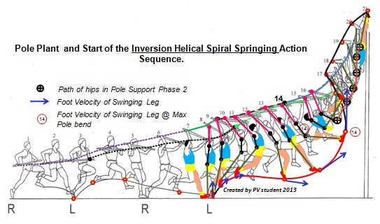
Tangential Velocity (m/sec) is angular velocity (rads/sec) multiplied by length of the radius in metres. Angular momentum is moment of inertia (mass (kg) x radius (m) x radius (m)) multiplied by angular velocity (rads/sec). Lengthening the leg swing radius without losing angular velocity will result in a proportional increase in linear tangential velocity.In the Bubka vaulting sequence shown below maximum angular momentum occurs around the snapshot instant depicted in image 13 and the maximum foot tangential velocity occurs during maximum pole bend and the start of pole recoil. The path of the hips (black cross circle) is predominantly vertical upward from maximum pole bend until the start of the inversion turn at instants 20-21.

- Bubka Dijon Petrov Model.jpg (70.01 KiB) Viewed 32307 times
Thus the advantage to this form of inversion swing is that the momentum vector direction of the vaulter’s COM and that of the pole recoil impulse (average recoil force x time) are parallel and both act simultaneously in a primarily upward direction. The vertical velocity component of the vaulter’s COM reaches a peak close to the time at which pole chord lengthening is coincident with the longitudinal axis of the pole (recoiled fully to its un- flexed resting length). This is due to the conservation of angular momentum about the local axis of rotation being coupled in time and spatially coordinated with the pole recoil force vertical component to cause the vertical rise of the COM in the curvilinear pathway from the instant of radius length L4 until L8 when pole release occurs as shown in diagram 1.This effect is further enhanced by the vaulter’s straight inverted body held in firm alignment with the vaulter’s longitudinal axis and maintained in close proximity to, and in parallel with, the rotational displacement of the chord and longitudinal axis of the pole during pole recoil.7. Previous discussion in this thread has focussed attention on the conservation of energy or momentum of the vaulter but
has not clearly elucidated how this is used to continue propulsion of the total system about the remote pole tip axes located in the planting box.Diagram 1 shows the relative changes in radial lengths from the vaulter’s COM to both the local and remote axes of rotation.
COM to Local Axis is Green Line L1-L8.
COM to Remote Axis is Red Line R1 – R8.
Note in reviewing diagram 1 the vaulter COM radius (L) shows a decrease in length from take-off until about instant 6 after which it slightly increases in length until pole release L8.(a) From take-off, until about instant 6 and the start of the vaulter’s half turn, the rotation of the vaulter is in a clockwise direction. This is opposite to the anticlockwise direction of the total system rotation about the pole tip.
(b) The vaulter rotation direction about the local axis at the top hand grip is changed by the 180 degree turn in combination with the spiral movement upward such that the vaulter’s COM passes above the level of the top grip. At about the time this occurs the vaulter’s COM rotation becomes concordant in direction (+ve anticlockwise) with that of the pole chord about the pole tip remote axis in the deepest point of the box.8.
The COM to the Remote Axis Radius (R) needs to be examined carefully in relation to the changing moment of inertia of the vaulter’s COM with respect to this axis and the curvilinear pathway during both phases of pole support.
Note the radial distance (R) of the vaulter’s centre of mass to the remote pole tip axis is shown clearly in the diagram to be a major determinant in creating the potential for “stalling” the anticlockwise rotation of the total system about the pole tip.
This stall potential is reduced when the “approximately 180 degree spiral turn” is completed quickly and an additional “torque couple” is created by the vaulter that acts in the same direction as the total system angular momentum.
The vaulter achieves this desired outcome by means of a “ pumping a playground swing type action” around the vaulter’s top grip fulcrum timed to adds some angular momentum to rotation around the pole tip even though the radial length R to the vaulter COM is increasing.
[i]The timing of the directional change of vaulter angular momentum is critical to successfully lowering the rate at which vertical velocity decreases whilst the total moment of inertia of the system about the remote axis is getting larger from maximum pole bend to pole release.
The radial length R increase from maximum pole bend to pole release is revealed to be much longer than the reduction in length of radius R from take-off to maximum pole bend.The following posts will address these considerations in more detail.In the next post I will first discuss the challenge posed by the moments of force (torques) opposing vaulter muscular effort. I illustrate the fact that the
vaulter weight force (-mg) induces varying magnitudes of the torques that the vaulter must overcome by swing power and swing amplitude in conjunction with vaulter controlled specific body actions (especially of the shoulders and hips).
Vaulter whole of body segmental configurations and alignment with respect the top hand grip local axis (Z) and the longitudinal axes (Y) of both the vaulter and the pole will also be explained.
Secondly I will propose some advantages that can be gained from the whole body “inversion and longitudinal turn technique employed by Bubka” which is based on the application of
Principles of Raising an External Weight by Turning a Helical Screw Between Two Relatively Fixed End Load Bearing Points to cause vertically upward linear translation of an external object (the vaulter).
Attempting to unravel the how and the why the inversion into the turn is mechanically effective in what I define as the
Helical Screw Turn Model of Using Vaulting Pole Recoil (PB Technical Model as demonstrated by Bubka) in contrast to the equally effective use by Renaud Lavillenie of what I define as a
“Trebuchet Type” Underswing Toe Shoot with Half Turn Model of Using Vaulting Pole Recoil, I will share evidence to
reveal that Renaud Lavillenie's 6.16m (indoors) vault is not an enigma.


